As wind turbines grow taller and more powerful, their foundations face unprecedented stress. This article explores three innovative strategies—from grout troughs to additional fatigue data—that can future-proof the critical tower-to-foundation connection. Smarter design choices today can deliver reliable, cost-effective projects in the coming years.
This is an exciting time to work in the wind energy industry. In a quarter century, the industry has literally grown up before our eyes. Towers that once stood 250 feet above the hills and prairies now extend nearly 450 feet high, with rotor diameters of 500-plus feet, more than twice their average length 25 years ago. It’s great news for our power supply, but it puts more stress on the critical connection between the steel tower and its concrete base.
As traditional design and construction methods approach their limits, the industry needs adaptive design and construction solutions. All of us have a role in future-proofing the tower-to-foundation interface.
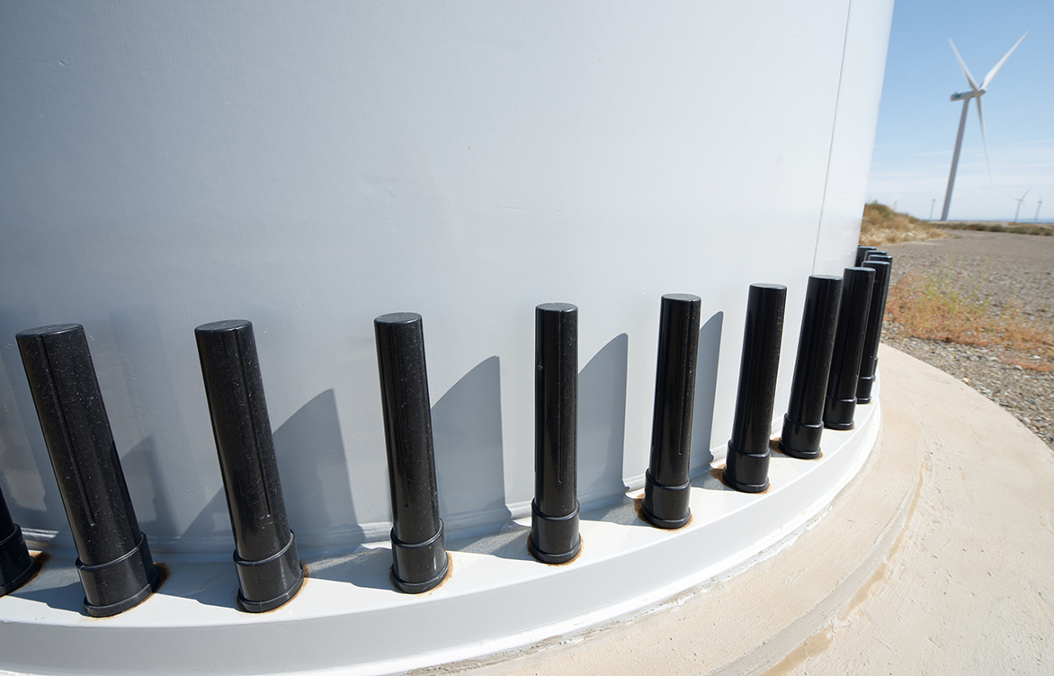
As the foundation loads increase, the diameter of the base flange—the flat, steel ring that connects the tower to the foundation—hasn’t grown much. Why? Tower sections can be only so wide and still be transported by truck down a roadway. So, to handle the extra load, designers add more anchor bolts and holes. However, this reduces the contact area between the flange and the grout, increasing the pressure.
Larger turbines also test the strength of their concrete foundation and the grout that attaches concrete to steel. A load-spreader plate (LSP)—essentially a huge steel washer installed under the tower flange—offers a partial solution by distributing the load and reducing demand on the underlying concrete. However, LSPs are expensive and currently not permitted by at least one major turbine manufacturer.1
As traditional design and construction methods approach their limits, the industry needs adaptive design and construction solutions. All of us—designers, manufacturers, material suppliers, and construction contractors—have a role in future-proofing the tower-to-foundation interface. Here are three recommendations that can help us get there.
1. Consider a grout trough.
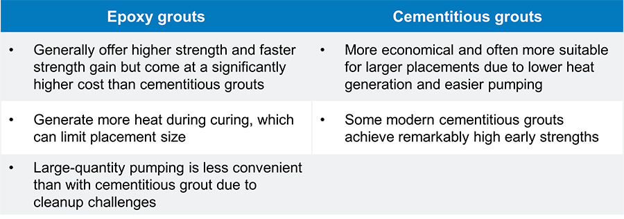
Grout—either epoxy-based or cementitious—is the common choice to transmit the load between the concrete pedestal and the steel tower flange. Measuring about 3 inches thick and extending about 3 inches beyond the inside and outside of the flange, a grout bed is a simple, familiar, and widely used method. However, it doesn’t always perform as designed. The choice of grout material also presents trade-offs, as shown below.
Grout type and placement considerations
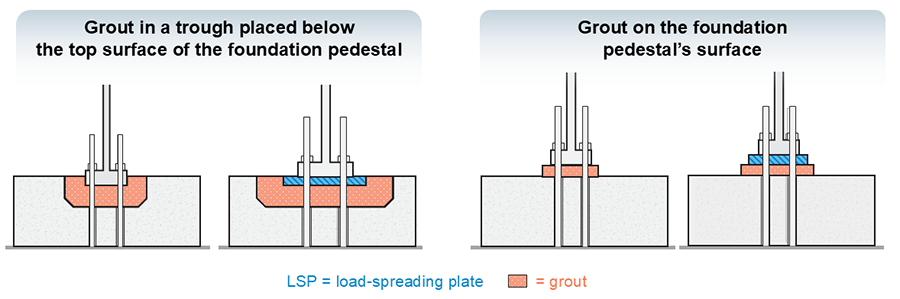
A common side effect of traditional grout placement is the spalling of unconfined 90-degree corners of the grout bed. While often not structurally critical, this can be unsightly for owners and operators, leading to inspections or costly cosmetic repairs. Non-shrink grouts are designed to be confined, and limiting the shoulder extension beyond the base flange to 2 or 3 inches can help prevent hairline cosmetic cracks in—or even curling of—the grout. However, this constraint can pose a challenge to effective load spreading, which may necessitate higher pedestal concrete strengths. Wind turbine foundation grout shoulders are often required to exceed the recommended width, thereby increasing the risk of cracking.
For a more robust design, consider a grout trough installed below the top surface of the pedestal concrete. A trough with sufficient depth and width beyond the tower flange (or LSP) and with vertical sides will effectively confine the grout, allowing further reduction of required pedestal concrete strength while minimizing cosmetic cracking. Cementitious grout is likely the favorable choice over epoxy when constructing a trough2 due to the cost and placement thickness limitations of epoxy resulting from heat generation.
Grout troughs, often facilitated by sacrificial foam molds, are the preferred and most common option for wind turbines in Europe.3 However, they haven’t caught on as widely in North America due to their perceived constructability challenges. It’s time we give them a closer look. The strategic use of a grout trough and a load-spreader plate (when permissible) is an excellent alternative to mitigate the need for excessively high concrete pedestal strengths.
2. Grout vendors should consider publishing characteristic cylinder strengths for their products.
The real challenge isn’t initial strength. It’s how grout resists fatigue from repeated cyclic loading.
Another key aspect of this interface challenge is how the grout performs over time, as wind turbines are subjected to repeated stress from cyclic loading. The industry term is “fatigue.” Grout suppliers in North America quantify their grout material resistance to fatigue by testing the level of stress at which the grout will crush two-inch cubes. However, there’s a catch: the industry design standard—DNV-GL-ST-C502 (or simply, “C502”)—wants strength data based on cylinders, which break more easily due to their shape. So, engineers apply a reduction factor to comply with the design standard. There are four additional reductions applied to the cube strength (five total). We think there are opportunities to refine three of these reductions, which could allow designers to reduce grout-strength requirements.
Our first two proposed refinements address the cylinder tests and the calculation of fatigue demands.
It is well-documented that cylinders break at lower stress levels than cubes due to their height-to-width aspect ratio, which differs from that of cubes. The code suggests a 20% reduction to account for this difference. While Eurocode 2 Table 3.1 offers slightly higher ratios of cylinder strength to cube strength, obtaining actual cylinder strength data directly from manufacturers would provide the most accurate characterization of their material, potentially resulting in lower strength requirements.
C502 fatigue-demand calculations require comparison with a characteristic strength of a cylinder (fcck), not just an average. The current vendor strength data provided is understood to be a straight average, which does not inform the foundation designer about its statistical reliability. Instead, if manufacturers provided their grout’s characteristic value—a strength below which only a small portion, typically 5 percent, of all tests are expected to fall—we could more accurately characterize its reliability and potentially limit its material-strength reduction for the fatigue-demand calculation.
3. Grout vendors should provide a “C5” value based on specific test data.
Adopting grout troughs and encouraging additional data from grout suppliers isn’t just about compliance. It’s about building more cost-effective and durable foundations for the next generation of wind turbines.
Another critical factor is the “C5” adjustment from C502, typically a 20% reduction applied in the absence of specific test data of the material’s fatigue performance. Some products demonstrate better fatigue performance than others, and reporting this test result directly could prevent unnecessary downgrades in fatigue strength. Some forward-thinking vendors are already providing these critical values.
Adopting grout troughs and encouraging additional data from grout suppliers isn’t just about compliance. It’s about building more cost-effective and durable foundations for the next generation of wind turbines. These changes reduce risk, improve reliability, and help the industry keep pace with a rapidly evolving industry.
Tailored solutions for your project
Defining the journey ahead depends on meeting the challenges of today. From the earliest days of the wind energy industry, Barr has been at the forefront of innovative problem-solving, helping shape the evolution of turbine foundation design. As towers grow taller and the demands on the tower-to-foundation interface increase, we’re dedicated to unlocking tailored options for every project, empowering contractors and owners to choose the best solution for their needs.4
For help sorting through your options for the tower-to-foundation interface, contact our team.
Footnotes
1 Some installers favor LSPs because they enable grout installation and plate setting without the need for a crane, thereby streamlining the construction process. This enables a single, larger crane to set all tower sections simultaneously, rather than requiring multiple cranes.
2 The grout trough does not inherently necessitate a larger volume of grout. Rather, it enables a larger grout placement (and associated load spread) before cracking/curling would otherwise occur in an unconfined grout pour on the top of the pedestal.
3 We have observed that the EPC/BOP project delivery approach in North America differs from that in Europe, where the foundation design is more closely tied to the turbine manufacturer’s scope of work or supply. This may help explain the different grout approach.
4 Barr often shares a tower/foundation interface options menu explaining the different methods and sharing our understanding of the advantages and disadvantages of each approach. Barr also has tools in place to prepare options specific to each project based on the turbine(s) being considered for the project.
About the authors
Cordelle Thomasma is a senior structural engineer with over 20 years of experience providing design services and project management for wind-turbine foundation projects. His experience includes serving as project manager and engineer of record, designing foundations, and supporting construction for dozens of wind projects across the U.S.
Matt Johnson is a vice president and senior structural engineer with over 24 years of experience providing comprehensive project management, engineering, inspection, and computer-aided design and drafting services. His experience includes serving as project principal and engineer of record for numerous wind energy projects. Matt has worked on over 100 wind-power projects, representing more than 10,000 megawatts (MW) of generating capacity. This work includes the Pakini Nui wind farm in a high-seismicity volcanic region of Hawaii and the first North American pile-supported Jersey-Atlantic wind farm in brackish water outside Atlantic City, New Jersey.
Joel Bahma, vice president and senior structural engineer, provides mechanical and structural engineering services, including analysis and design, forensic evaluations, and computer-aided design and drafting for wind power and other renewable-energy development projects. He has served as a design engineer and project manager for wind-turbine foundations on more than 80 wind-power projects across the country and has contributed to 150 completed wind-power projects. In addition to design projects, he has served as a structural engineer for pre-construction assessments, inspections of structures, and post-construction inspections.